Vision System
An industrial machine-vision system that tunes itself. A toolbox of vision Tools running under one loop that improves each one from a verification signal, instead of hours of manual tuning.
This is a proof of concept and still under active development. The architecture and results described here may change as it evolves.
The problem
Commissioning a machine-vision inspection station is slow, and the slowest part is tuning. Every new part means an engineer hand-adjusting thresholds, regions and lighting parameters by trial and error until the inspection is reliable. On the factory floor I've watched that eat hours per station — and it has to be redone whenever the part, lighting or batch changes.
I wanted a vision system where the tuning tunes itself: you tell it what "good" looks like, and it converges on the parameters instead of you doing it by hand.
How it works — the tuning loop
The system is a toolbox of Tools, each a single vision capability you select and configure. Sitting above them is a adaptivemeta-layer that improves a Tool's parameters or model from a verification signal: an automated right/wrong measure, such as accuracy on a labelled set, or an operator confirming a reading. It's the same idea behind autonomous-research loops, applied to vision instead of robot policies.
The loop improves a Tool in one of three ways:
Fits an ML Tool's model on accumulated, operator-confirmed labels.
Optimizes a Tool's parameters — edge/score thresholds, OCR pre-processing — against the verification signal.
Learns a reference pattern and accept threshold from known-good samples, averaging the part's real matched region across frames into a denoised reference.
The three Tools
OCR Reader
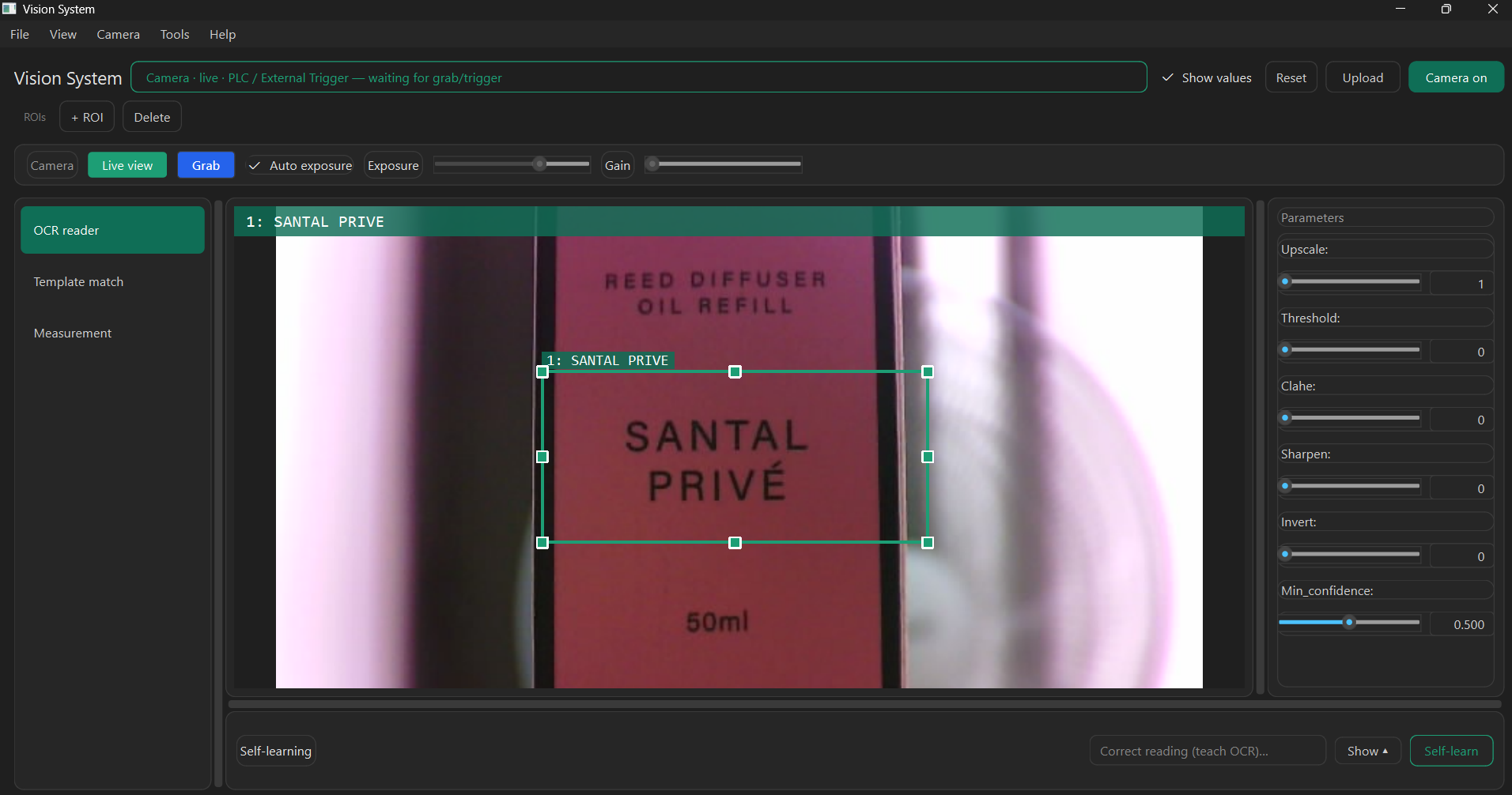
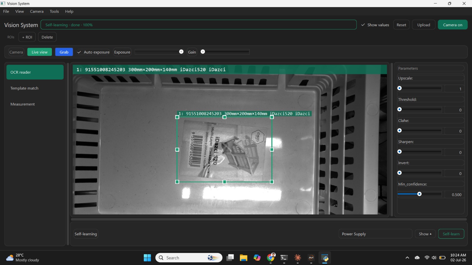
Machine learningReads serial numbers, date codes and part markings using a pretrained recognition model (RapidOCR). It self-learns by searching over image pre-processing (upscale, threshold, CLAHE, sharpen, invert) against the operator's confirmed reading, so it adapts to a new part's lighting and contrast without anyone editing parameters.
Measurement
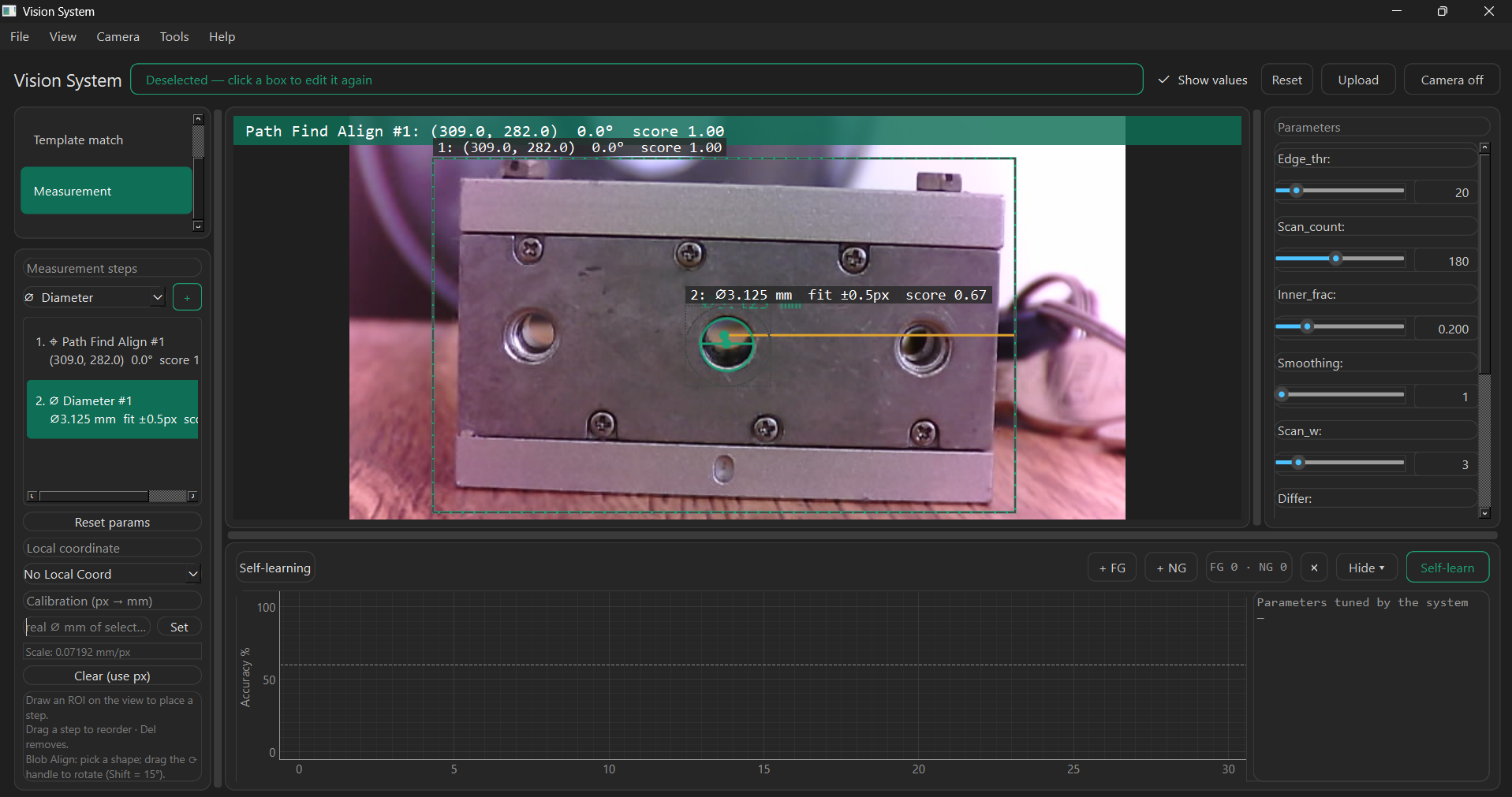
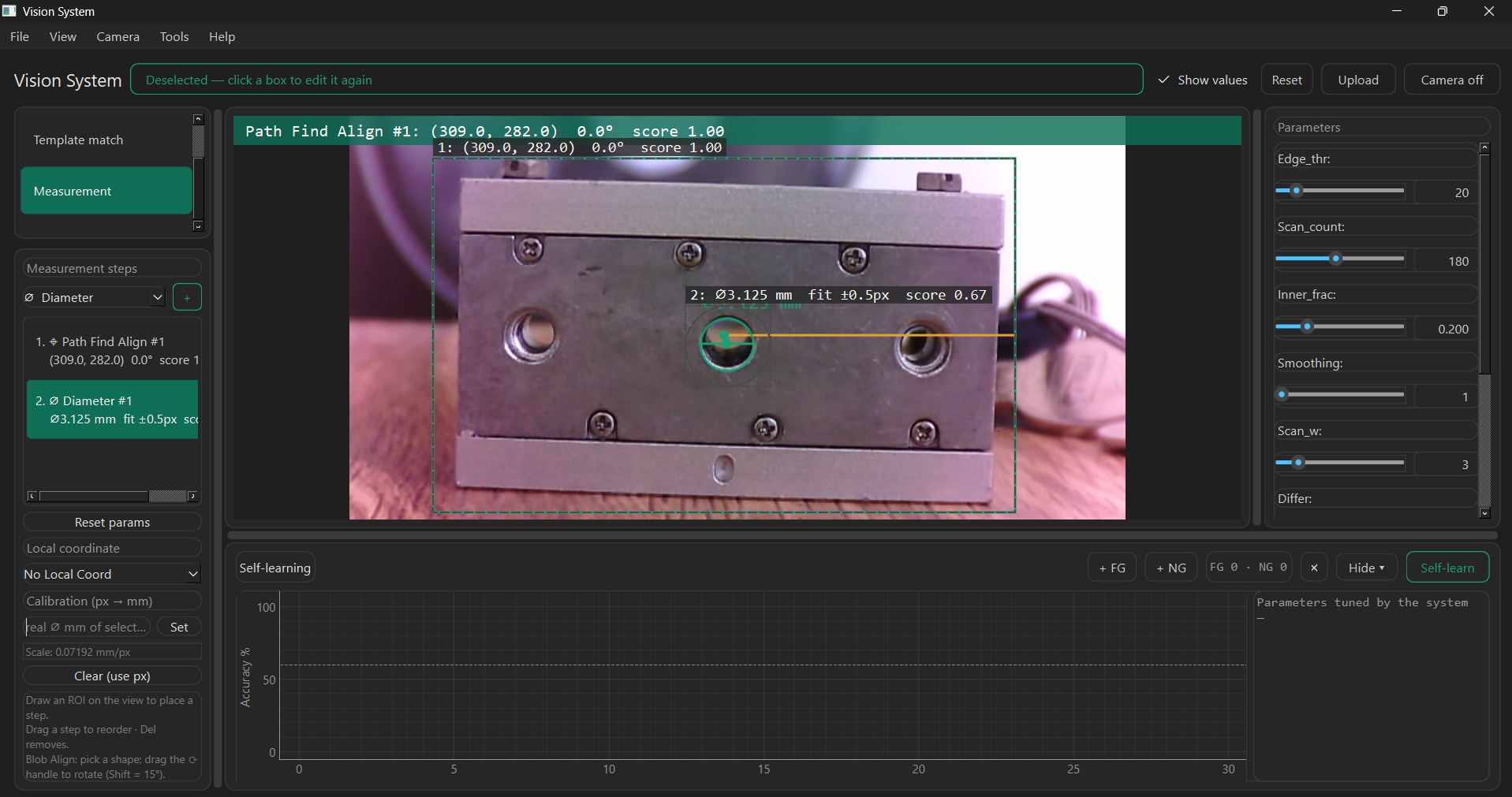
Classical CVA dimensional-metrology Tool built as an ordered pipeline of measurement steps: Circle Align and Path Find Align establish a datum, then Diameter and other steps report dimensions linked to that datum so each region follows the part as it moves. It replaced a rigid single-caliper approach with a composable pipeline.
Template Match
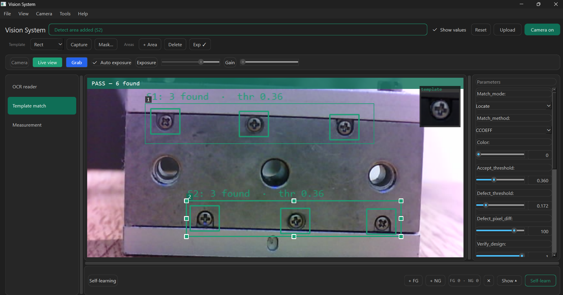
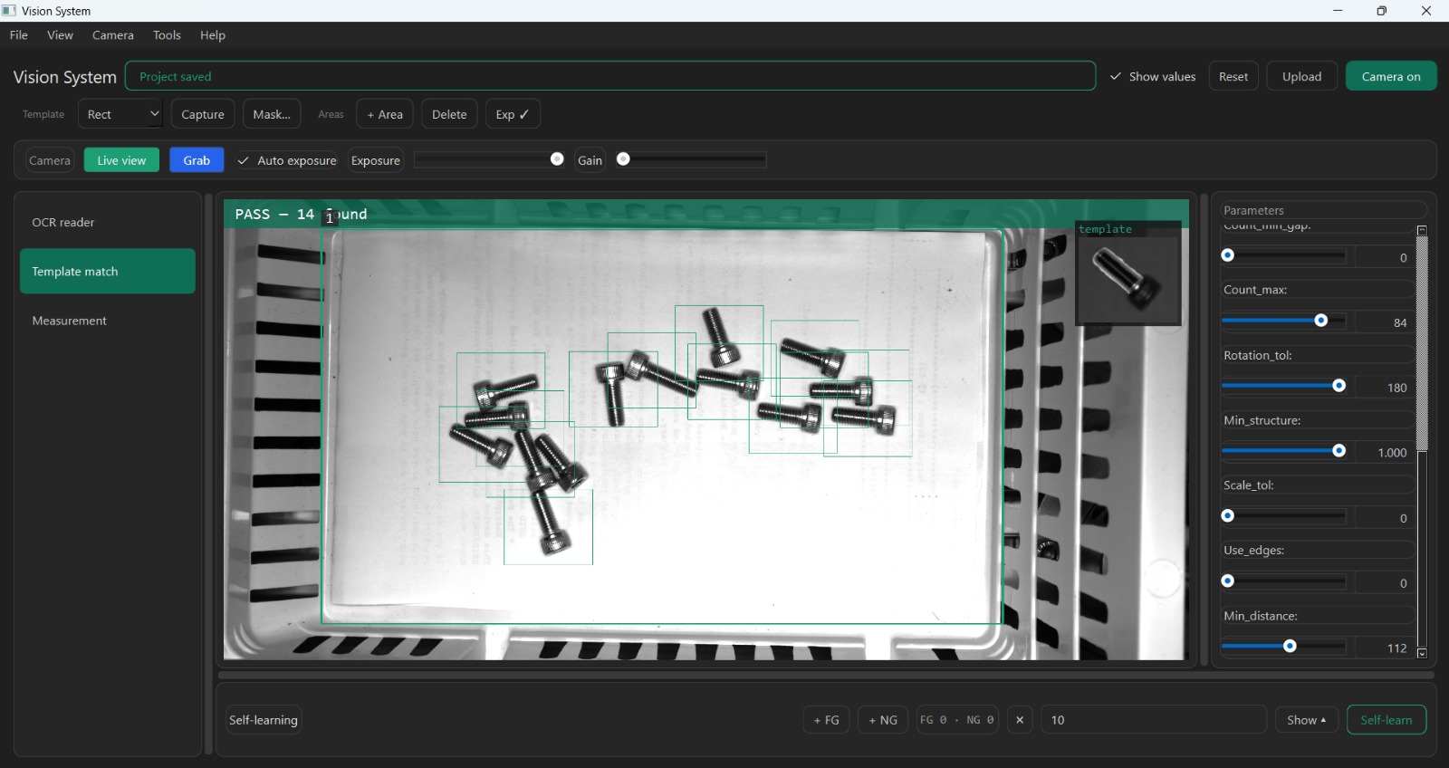
Classical CVCaptures a reference pattern (the exemplar) by dragging a box on the live image, then finds it across the frame. It runs three ways: Locate (is the pattern present, and where — including per-area present/absent checks), Count (how many), and Inspect (flag the part good or flawed against the reference).
Talking to the line — environment settings
A vision algorithm is only useful on the floor if it can plug into the machine: trigger on the part, hand a pass/fail back to the PLC, and keep a record. That's what the Environment Settings do: a tabbed editor where every tab is wired to real behavior, not a mockup. It's the part that turns the tool into an actual inspection station.
Sets the device, resolution and exposure/gain — and the grab mode: Continuous, Software Trigger (one part per button press), or PLC / External Trigger, where the line's part-in-position signal fires each inspection. The live view never stops.
The app runs a TCP server and emits one line per inspection — e.g. OK <value> — to any host, PLC or test tool that connects. Configurable line terminator, separator and send mode (every result, on change, or NG only).
Writes a 3-register block per result in a single transaction — verdict (good/NG), a scaled measurement value, and an incrementing counter — so the PLC always reads a consistent snapshot. Runs as Modbus master, or as a slave the PLC reads directly, smart-camera style. An optional PLC-triggered mode lets the PLC request an inspection and read the result back.
Appends every result to a dated CSV (timestamp, verdict, value) and optionally saves both the raw frame and the overlaid result image — all results, NG only, or off.
Sends serial on/off commands to drive an inspection light or simple IO, so lighting is part of the recipe rather than a manual step.
Log level and location for diagnostics — so issues on the floor can be traced after the fact.
The optional integrations are safe to skip. If the Modbus or serial libraries aren't installed, those tabs still save their config and no-op with a clear message, so the app runs anywhere.
Built with
Right now it's a working proof of concept: the three Tools above, with the tuning loop running. The code is private, but I'm happy to walk through the architecture and a live demo.